
The gap between a 3D file and a shipped container is not a production run. It is seven separate transfers of responsibility, and every one of them can silently break without anybody noticing. A buyer who treats the file-to-shipment path as a single step learns about a problem at the point where it costs the most to fix. A buyer who can name the stage, the owner and the deliverable at each hand-off knows exactly where to look when a sample arrives late, a mould is cut wrong, or a plated batch arrives a shade off the approved sample. This guide walks that path stage by stage, with the process parameters that actually constrain each stage and the tolerances the industry publishes for them.

Quotes for custom metal souvenirs arrive as a unit price and a lead time, and both are difficult to compare because the underlying scope differs. One supplier’s quote includes a soft mould and a pre-production sample; another’s includes only the casting run, with tooling quoted separately and the buyer responsible for approving a hand-moulded model first. A third quotes the same unit price on the basis of an existing mould the buyer has never seen. The unit price is identical in all three cases. What changes is how much of the engineering work sits inside it.
That is the reason this breakdown exists. Below is the path a custom metal souvenir actually travels, from the file the buyer supplies to the carton that leaves the factory, broken into seven stages. For each stage there is a named owner, a defined deliverable, and the published process parameters that limit what can be achieved. The point is not to turn a buyer into a die caster. It is to let a buyer read a quote and know which stages are inside it.
Stage 1 and Stage 2: the file and the manufacturability review
Every order starts with a file, and the file is almost never production-ready. Buyers typically supply a 3D model created for rendering, or artwork drafted in a 2D vector program, or a photograph of a physical object. The factory’s first job is to determine whether the geometry can be produced in the chosen material, and to establish what has to change for it to be producible.
Zinc alloy is the dominant material for metal souvenirs and awards because it fills thin sections and holds fine surface detail better than other die-casting metals. The published reference values for Zamak 3, the most widely used grade of the alloy family, give the process envelope: melt temperature 415 to 435 degrees Celsius, die temperature 165 to 220 degrees Celsius, injection velocity at the gate of 20 to 50 metres per second, intensification pressure 140 to 350 bar, cycle time 4 to 8 seconds for typical parts, shot weight 5 g to 1.5 kg, and a minimum wall thickness of 0.4 to 0.6 mm achievable in production tooling.
Wall thickness is the number that most often changes during this review, because a model designed for visual appeal rarely accounts for the metal’s flow behaviour. A 0.3 mm fin that looks elegant in a rendering may not fill. A deep pocket with a sharp internal corner may create a core shift. These are not defects introduced later; they are consequences of the geometry that was approved. This reference on Zamak alloys and hot-chamber die casting sets out the fluidity limits, the solidification behaviour and the impurity thresholds that constrain those choices.
Draft angle is the second mandatory correction. Parts must release from the die without dragging. A model with zero draft on a vertical wall is a model that will show drag marks, tearing or a broken die face, and the fix is applied by the factory rather than by the buyer, which means the part’s outer dimensions shift by a fraction. Buyers who want to work ahead of the factory rather than react to it can study existing geometry in a public library of manufacturing models, such as the GrabCAD library of CAD models, to see how published parts handle wall thickness and draft. The international standard that governs these allowances is ISO 8062-3:2023, the third part of the geometrical product specifications series covering dimensional and geometrical tolerances for moulded parts. It specifies general dimensional and geometrical tolerances and machining allowance grades for castings expressed with plus or minus tolerances for indicated dimensions, and it is applicable to castings in all cast metals produced by various casting processes.
Two features of that standard matter commercially for a buyer. First, it applies to dimensions that carry an indicated tolerance. A 3D CAD model with no dimensional indications is explicitly outside its scope, which means a file floating in an email carries no tolerance contract at all. Second, the standard separates general tolerances, which apply by default to the drawing, from individual callouts that override them, so a drawing that specifies nothing inherits a tolerance band the buyer never chose. Requesting a drawing with indicated dimensions is what moves the tolerance question from the supplier’s default to the buyer’s specification.
Table 1 sets out the seven stages. The owner column matters more than it looks: at every stage exactly one party is accountable for the next deliverable, and every handover is a place where a file silently changes hands without anyone signing for it.
| Stage | Owner | Deliverable | What can go wrong here |
|---|---|---|---|
| 1. File intake and DFM review | Buyer + factory engineering | Reviewed model with annotated changes | Buyer approves geometry that cannot fill or will not release from the die |
| 2. Technical drawing and tolerance confirmation | Factory engineering, buyer signs | Dimensioned drawing with indicated tolerances | No tolerance contract exists, so the factory’s default governs |
| 3. Soft mould prototype | Factory tooling room | Machined or printed soft-mould sample | Sample judged on surface texture rather than on form |
| 4. Hard steel mould | Factory tooling room | Hardened steel die and first tool shots | Walls revised during cutting silently change the outer envelope |
| 5. Pre-production sample and finish approval | Factory finishing + buyer | Plated sample against a signed finish reference | Colour approved on an unplated part, or on a screen |
| 6. Mass production run | Factory production | Cast, machined, plated, assembled lot | Batch shifts from sample because alloy or plating bath changed |
| 7. Final inspection, packing and dispatch | Factory QC + buyer inspection | Inspected, packed, shipped consignment | Acceptance criteria never written down, so acceptance becomes a negotiation |
Stage 3: what a soft mould proves and what it does not
The soft mould is the cheapest way to find out whether the form works, and it is frequently over-read. A soft mould is machined, usually from a machinable plastic or a printed master, and it reproduces the geometry without reproducing the process conditions. It shows the shape, the parting line, the location of features and the general feel of the part. It does not reproduce the fill behaviour of molten metal, the ejection temperature, the skin that forms against the die face, or the plating surface that follows from those.
That distinction matters because the properties buyers most often judge on a soft sample are precisely the ones that change most in production. Weight changes with the alloy and the wall thickness that the die actually achieves. Surface texture changes because the production part carries a dense outer skin and is polished against a hardened die rather than a plastic master. Colour changes because the plating sits on a different base metal with a different crystal structure underneath.
Additive manufacturing and CNC machining sit on either side of this distinction, and the comparison is worth understanding before a buyer orders the wrong kind of pre-production model. A fused filament fabrication part printed in ABS can be only about 10% as strong as solid ABS, while a selective laser sintered part in nylon can reach close to 100% of solid nylon strength. CNC machining, by contrast, removes material from a billet and delivers the native properties of the engineering material undisturbed by the process. The full comparison between the two approaches is set out in this guide to 3D printing versus CNC machining, which also covers the stepped surfaces that layer resolution produces on sloped or curved faces. For a metal order, the practical rule is that a printed master proves geometry and a machined master proves geometry with real material behaviour.
Stage 4: the steel mould and the parameters that bound it
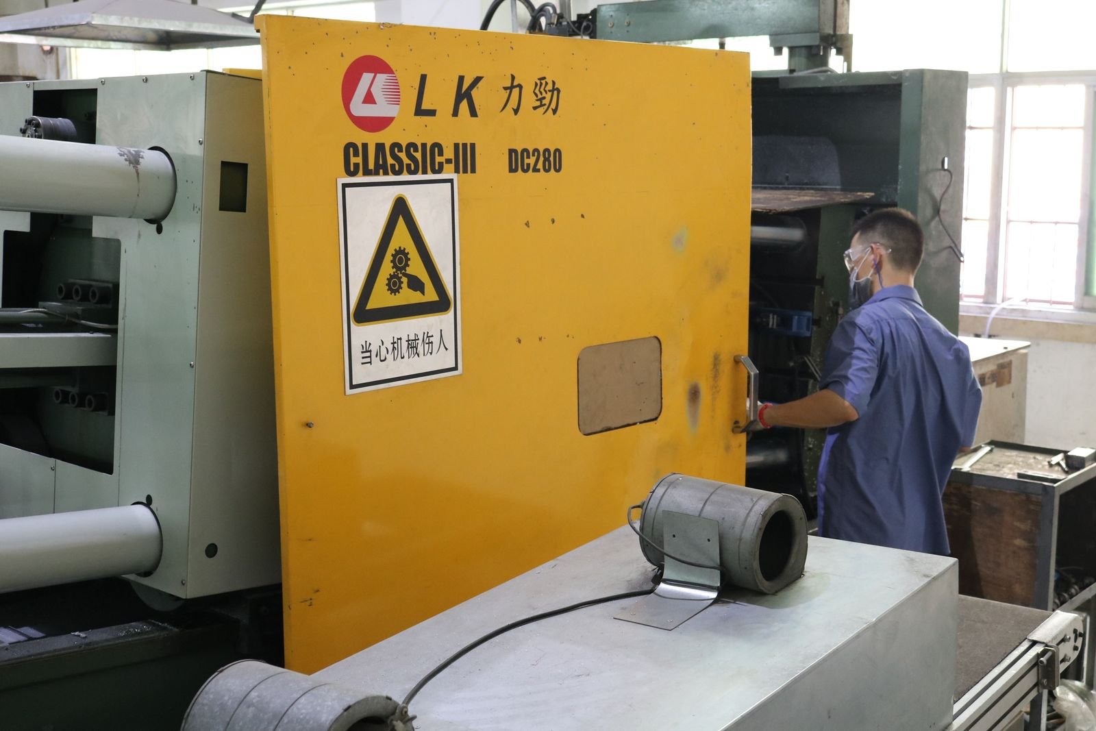
The hard mould is where most of the money and most of the risk sit. The die is machined from tool steel, hardened, and then adjusted by trial shots until the part comes out consistently. During this stage the factory is making decisions that the buyer is usually not present for, and each decision moves the part relative to the approved model.
The metals involved behave in ways that reward attention. Zinc die casting is described as the highest-volume precision metal casting process by number of parts produced, because zinc’s liquidus near 380 to 390 degrees Celsius, its fluidity and its low solidification shrinkage allow tighter tolerances than other die-casting metals achieve. Nadcast product standard general tolerances for Zamak 3 are given as plus or minus 0.05 mm on dimensions up to 25 mm, with critical tolerances reaching plus or minus 0.025 mm, against plus or minus 0.10 mm general for aluminium high pressure die casting. Surface finish follows the same pattern, with Ra values of 0.4 to 0.8 micrometres for zinc against 0.8 to 1.6 micrometres for aluminium.
Those numbers describe an as-cast part. Any dimension the buyer expects to be tighter than the casting tolerance has to be machined after casting, which is why the machining allowance is written into the drawing and why a buyer who changes a dimension during the tooling stage pays twice. A useful reference for the defects that appear once these parameters are set is this guide to die casting defects, which covers the porosity, flash and warping problems that show up when fill, venting or thermal balance are wrong.
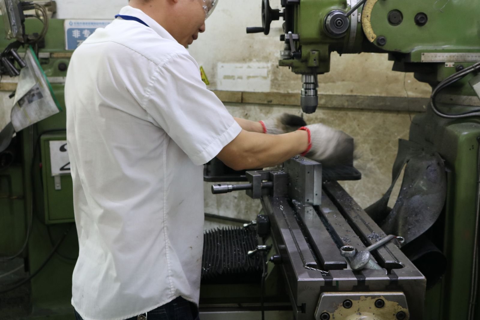
Two process details deserve specific attention from a buyer who is judging whether a supplier knows its own process. The first is the skin. In a hot-chamber zinc casting, the outer skin between 0.1 and 0.3 mm below the surface solidifies almost instantaneously against the die face and is free of porosity and segregation; the core solidifies more slowly and may contain fine interdendritic porosity. Any machining that removes the skin exposes the coarser core and severely degrades plating adhesion and corrosion resistance. The practical rule that follows is simple: drilling, tapping and milling for assembly must be confined to surfaces that will not be visible in the finished product, because visible surfaces must stay in the as-cast condition to accept plating.
The second is ageing. As-cast zinc contains a supersaturated solution that decomposes over days to weeks at ambient temperature, producing a net linear contraction of 0.01 to 0.07% depending on grade and section thickness, stabilising within 3 to 5 weeks. The dimensional data published for the grades show Zamak 3 changing by about 0.005% at 24 hours and about 0.042% at 96 weeks, while the copper-bearing grades move further. The consequence for a buyer is precise: measuring an un-aged casting to a tight tolerance produces a false accept, because the part will subsequently move out of tolerance in service. For precision parts the standard response is stabilisation annealing at 70 to 100 degrees Celsius for 3 to 6 hours immediately after casting, which completes the decomposition so the part can be machined or inspected to final tolerance with no further drift.
For decorative souvenir work the practical consequence is smaller but still real. A 60 mm medal with a nominal thickness of 2.5 mm loses 0.02% of 2.5 mm during ageing, which is well under a tenth of a millimetre. A tight-fitting component that depends on the casting being exactly at size, a lid that has to drop into a recess, a hinge barrel that has to align, is a different matter. A supplier who knows the alloy will either specify a stabilisation step or tell you that the part should not be measured to final tolerance until it has aged.
Stage 5: finishing and the finish reference
Finishing is where the buyer’s approval habit has the biggest effect on the outcome. The colour and gloss that get approved should be approved on a real plated part, against a written reference, because plating colour is the result of a chemistry stack rather than a pigment choice. The standard decorative sequence for bright chrome on a zinc casting runs copper strike at 3 to 8 micrometres, bright acid copper at 15 to 30 micrometres, duplex nickel at 8 to 15 micrometres and chromium at 0.2 to 0.5 micrometres. Each layer changes how the next one reads.
Two categories of finish are commonly quoted for these products, and the distinction is technical rather than cosmetic. Electroplated finishes in gold, silver, rose gold, antique brass, antique silver, antique copper, black nickel and dual tone are produced by the stack above. Powder coating over a zinc phosphate conversion coating is a different route entirely: it is a thick film sitting on the surface, it tolerates the as-cast skin, and it produces a visually different result that cannot be matched by a plating reference photograph. Both are legitimate. A buyer who approves a powder-coated look against a gold plating photograph will be disappointed, and that disappointment is a specification failure rather than a production failure.
The written finish reference should state the plating or coating route, the colour standard, the surface appearance, and the areas where tarnish or wear is acceptable. The durability question is worth answering explicitly, because a souvenir that sits in a shop window and one that goes on a child’s wrist are different use cases. The technical background on how plated finishes degrade is covered in our guide to salt spray testing for metal finishes, which compares ASTM B117 with ISO 9227 hours and explains what those numbers do and do not promise.
Stage 6: the production run and the alloy that gets cast
The mass production run is where everything upstream either holds or does not. The published reference for the alloy family gives the share directly: Zamak 3 accounts for roughly 55 to 60% of all zinc die casting production, because the absence of copper gives the best dimensional stability, elongation and electroplating quality of the four grades. Zamak 2 and Zamak 5 add around 1% copper for hardness and creep resistance at the cost of larger dimensional change during ageing. Zamak 7 is the high-ductility variant with reduced magnesium. Each is a different alloy with a different specification and a different price band, and a quotation that does not name the grade is not comparable with one that does.
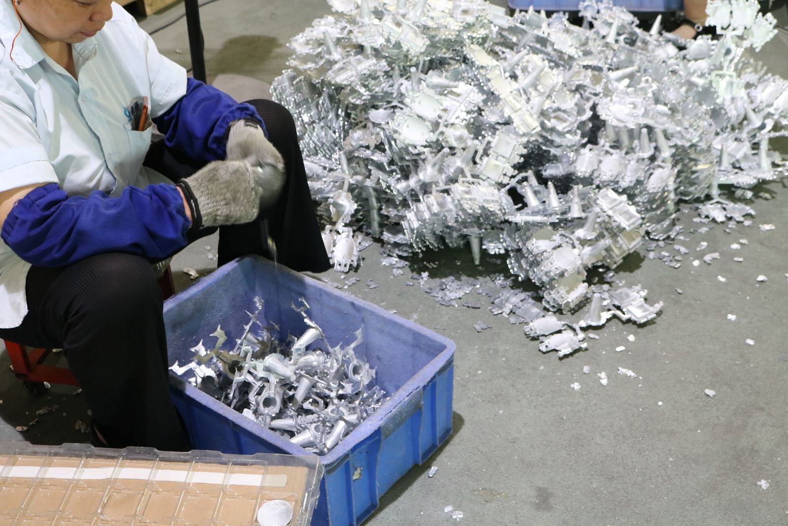
Material certification is the part of this stage that most often gets skipped. Zinc die castings are vulnerable to intergranular corrosion when lead, cadmium or tin exceed their thresholds, because these impurities segregate to grain boundaries during solidification and form continuous films that corrode preferentially in humid conditions. The published thresholds are lead above 0.004 wt%, cadmium above 0.003 wt% and tin above 0.002 wt%. The historical failure mode was called zinc pest, and the reason it became uncommon is that special high grade zinc of at least 99.99% wt% zinc came into use from the 1950s together with strict impurity limits in ASTM B86. Scrap handling is the practical risk, because remelting plated scrap directly into the casting furnace reintroduces the very contaminants that cause the problem. A factory that runs spectrometric verification on incoming material is doing something concrete and checkable; a factory that says it uses good zinc is not.
Note the magnesium detail, because it is the kind of thing that separates a specification from a slogan. Magnesium at 0.02 to 0.06 wt% plays a protective role against intergranular corrosion by forming fine magnesium-lead intermetallic compounds in the grain boundary region, sequestering lead impurities into discrete particles rather than letting them form continuous films. Below roughly 0.02 wt% magnesium that protection is incomplete, which is why the low-magnesium grade requires even tighter lead limits. If a supplier quotes a grade with reduced magnesium and does not explain the impurity strategy, that is a reasonable question to raise.
Stage 7: acceptance criteria and dispatch
The last stage is where the buyer’s protection is either real or rhetorical. By the time the goods are packed, everyone has agreed on the shape informally and on the finish informally, and the only mechanism that converts that agreement into an enforceable standard is a written acceptance criterion set and an inspection that applies it to the actual lot.
What belongs in that set is short: dimensional limits on the features that matter, the plating or coating route, the colour reference, the acceptable cosmetic defect thresholds, and the treatment of the reverse and edge surfaces. What belongs in the inspection is more specific still. A buyer who has not decided in advance how many pieces get inspected and how the result is judged has left the most expensive part of the transaction to chance. Our guide to control de calidad de los regalos metálicos personalizados covers the checks that run before shipment and how to convert them into written terms.
Timing is worth stating plainly because it is a common point of disagreement. Sampling a finished lot for critical dimensions before it has aged is not a valid measurement, and a buyer who inspects on the day of packing will record readings that later fall outside the tolerance band. Either the parts are aged before inspection, or the inspection measures a different set of characteristics than the one that matters.
What a quote actually contains
With the seven stages in view, a buyer can read a quotation properly. A quote that names a unit price and a lead time but does not mention tooling, sample production or finishing tells you that one of those is excluded, and you cannot tell which. A quote that names a soft mould sample and a pre-production plated sample has scoped stages 3 and 5, which is the most common structure for a first order of a fully custom design. A quote that separates the mould cost from the piece price has scoped stage 4 as a one-time charge, which is the normal structure once a design is reused across reorder.
Lead time follows from the same structure rather than being a standalone number. At Kingtop, sample production takes 7 days and mass production takes 15 to 20 days, and those figures describe the manufacturing stages at this factory rather than a universal commitment. A quote promising a faster route usually means fewer stages, and fewer stages usually means a design that is closer to an existing mould. The minimum order quantity structure works the same way: 100 pieces when an existing mould is used, 500 pieces for a standard design on an existing mould, and 1,000 pieces for a fully custom die casting. Each of those tiers corresponds to a different amount of design work, and the number is a signal about what the tooling will be shared across.
Two further points about scope are worth checking before a purchase order is issued. First, logo application sits on its own step, and the options differ in cost and in how they interact with a plated surface: laser engraving, screen printing, embossing, debossing, moulded logo and enamel colour fill are not equivalent. Second, the drawing and its tolerance indications are part of the deliverable, not a courtesy. Without them, there is no specification to inspect against and no basis for a claim later. If you want the argument settled in advance rather than after a container is on the water, ask for the dimensioned drawing with indicated tolerances at stage 2 and treat the signed copy as the contract document.
The material choice narrows this further. Zinc alloy covers most souvenir and award work, while stainless steel, brass and bronze, and iron are used where the buyer needs corrosion resistance, a different weight, a different plating response or a lower unit cost at volume. Each moves the process parameters above, and each moves them in a way that changes what the stage 4 tolerances can be. A supplier who quotes one alloy and delivers another has not made a small substitution. For the trade-offs between the main options, our guide to how custom metal gifts are made covers the process route end to end.
The stage handover matrix
What follows is the summary version of the path above, arranged so that a buyer can hold it next to a quotation and mark off which stages are inside. Each row names the party who owns the deliverable, the artefact that proves the stage was completed, and the question to ask if the answer is unclear. The matrix is deliberately specific, because a stage without a named artefact and a named owner is the stage where things go missing.
| Stage | Owner | Deliverable | Proof to request |
|---|---|---|---|
| 1. File intake and DFM | Buyer and factory engineering | Reviewed model, annotated change list | The annotated list, not a verbal summary |
| 2. Drawing and tolerances | Factory engineering, buyer countersigns | Dimensioned drawing with indicated tolerances | A signed copy, since an unsigned drawing is not a specification |
| 3. Soft mould | Tooling room | Machined or printed master sample | The sample itself, held by the buyer |
| 4. Hard steel mould | Tooling room | Hardened die plus first tool shots | Tool shots against the approved master |
| 5. Pre-production sample | Finishing and buyer | Plated sample and finish reference | A written finish reference, not a screen image |
| 6. Mass production | Production | Finished lot | Alloy certification and impurity analysis |
| 7. Inspection and dispatch | QC and buyer inspection | Inspection record, packing list, consignment | The inspection record with its sampling plan stated |
Used this way, the matrix turns a quotation review into a set of specific questions. Which stages are inside this price? Where is the tolerance contract written down? What artefact proves stage 5 was approved and on what reference? Where does the alloy grade appear? At which point does the responsibility for the result move from the factory back to the buyer? Those five answers will tell a buyer more about the reliability of a supplier than any capacity figure, lead time promise or sample fee on the quotation.
For buyers who need the same depth on the design side rather than the production side, our guide to the difference between 2D, 2.5D and 3D metal products explains which construction each design level actually uses and how it affects both the tooling path and the unit price. And for the practical floor on order sizes, our article on custom metal gifts MOQ sets out what each minimum order quantity tier means for tooling ownership and reorder flexibility.
Send your artwork or 3D file to sales@kingtopgift.com with your target quantity and finish in mind, and ask for the stage 2 drawing back before anything is cut. That single request is where most of the avoidable cost in a custom metal order is saved.