
Most die casting defects are not a mystery to a factory, they are a shortage of information on the buyer side. A buyer who cannot name gas porosity versus shrinkage porosity, or who never asked for a porosity grade in the region that actually matters, cannot tell a recoverable cosmetic issue from a batch that should be rejected. This guide walks through the zinc alloy die casting defects that appear on custom metal souvenir orders, what each one looks like in the hand, what causes it, and the exact wording to put into your inspection request so that a factory measures what you care about instead of what is convenient to measure.

Why zinc alloy dies behave differently from aluminium dies
Buyers often transfer expectations from aluminium die casting straight to zinc alloy, and the two metals behave differently enough that the same defect can have a different cause and a different fix. The difference starts with temperature. Pure zinc has a liquidus of 419°C, and adding roughly 4% aluminium as the primary alloying element pulls the working liquidus down to about 385–390°C. Aluminium’s liquidus sits above 580°C, which destroys the submerged steel gooseneck in a hot chamber machine and therefore requires a cold chamber machine for every aluminium job.
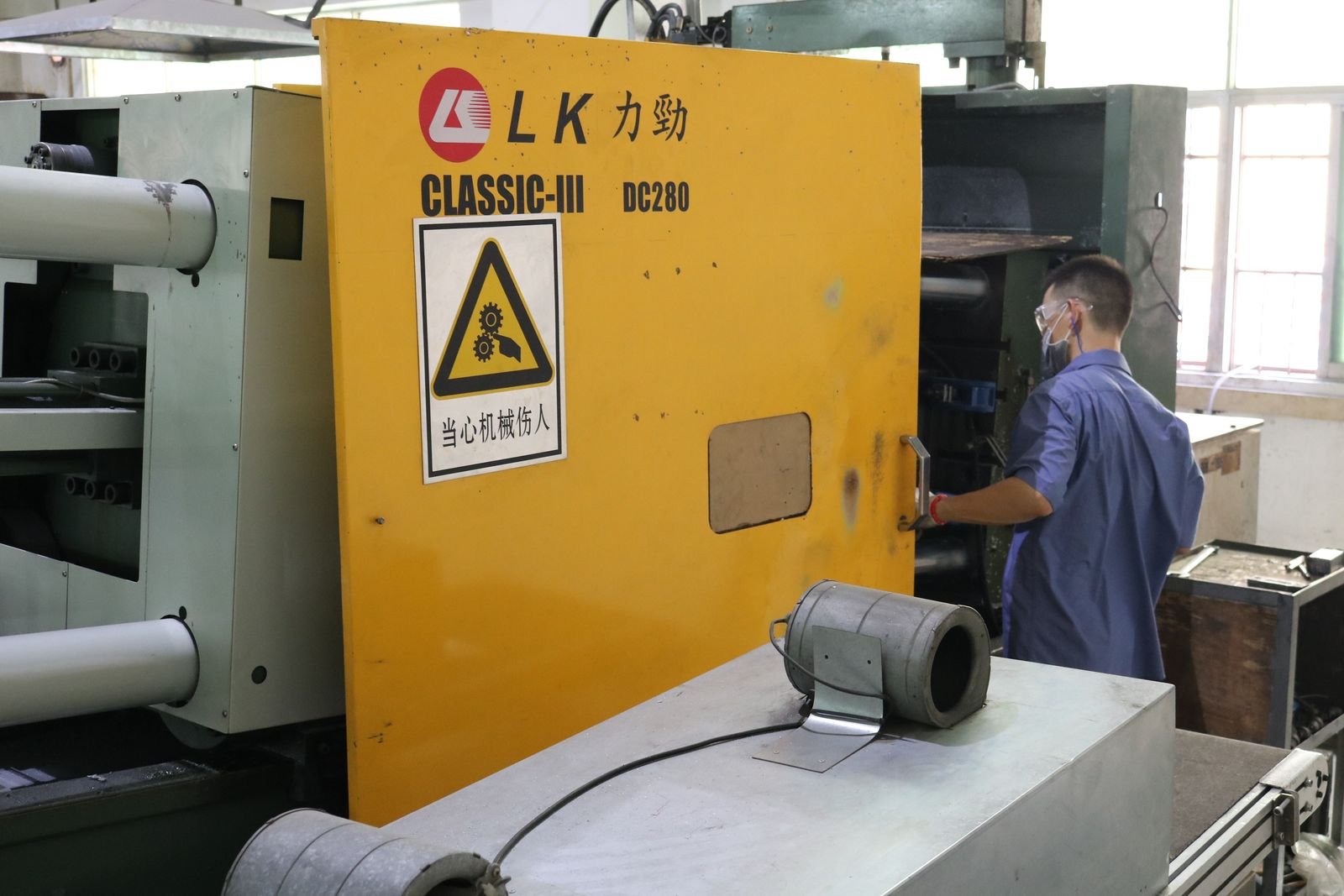
Because zinc alloys melt at such a low temperature, they run in hot chamber machines where the molten metal sits inside the machine’s own steel chamber rather than being ladled into it. This is not a small operational detail. It is the reason zinc alloy can hold a fine detail and a thin wall while remaining economical to run. The published figures for the two processes sit far apart: a typical zinc alloy die casting cycle runs in seconds and hot chamber zinc lines are reported to exceed 800 shots per hour, while sand casting is measured in hours per mould, because the mould has to be made, poured, cooled, shaken out and reclaimed before the next one exists.
Zamak 3 is the dominant grade, accounting for 55–60% of all zinc die casting production. It contains no copper, offers roughly 10% elongation, has the best dimensional stability of the family, and behaves as an excellent electroplating substrate, which matters constantly for metal souvenirs because plating is where a good casting becomes a retail product.
Fluidity is the other zinc-specific advantage. Zinc alloys have among the highest fluidity of any casting metal, which allows wall thicknesses down to 0.4 mm in production tooling. That thin-wall capability is a capability unmatched by aluminium or magnesium die casting alloys, and it is what makes miniature landmark models, thin coin-style medallions and small bag charms practical to cast rather than machined.
Two consequences follow for buyers. First, a zinc alloy part that comes out of the die is already close to net shape, so the defects you will argue about are internal ones and surface ones rather than machining ones. Second, the alloy families are formally specified: ASTM B86-23 covers the standard zinc alloy die castings, naming eight alloy designations including Alloy 3, 7, 5 and 2 as Zamak 3, 7, 5 and 2 with the UNS designations Z33525, Z33527, Z35533 and Z35545 used for pressure die castings, and ZA-8, ZA-12 and ZA-27 under Z35638, Z35633 and Z35841. The standard also notes that continuous cast bar is used for prototypes and for screw machine blanks. If your supplier quotes a generic “zinc alloy” with no alloy designation attached, you have no specification to inspect against, which is why the alloy name belongs in your purchase order.
The defects that decide whether an order is accepted
There is a small set of zinc alloy die casting defects that account for nearly every argument between a factory and a buyer. The table below names each one, describes what it looks like in the hand, states the primary cause, and gives a working severity judgement along with whether it is normally a shipping-acceptance issue or a rework item. The vocabulary matters: a buyer who writes “there are holes in it” gets a conversation about price. A buyer who writes “gas porosity visible on the reverse face in the lower third” gets a conversation about vent placement and a corrected shot.
| Defect | What it looks like | Primary cause | Severity | Normal disposition |
|---|---|---|---|---|
| Gas porosity | Rounded, smooth-walled voids just under the surface; surface may be pitted after plating or bake | Entrapped air, dissolved hydrogen, or lubricant vapour | Medium to high in visible zones | Reject if visible on a display face; accept inside a non-critical area only against a stated porosity grade |
| Shrinkage porosity | Jagged, angular or dendritic voids clustered in thick sections and bosses | Contraction during solidification with no feed path into the last-to-freeze area | High | Reject. It appears after machining and after heat treatment, so it cannot be repaired downstream |
| Flash | A thin fin of metal at the parting line, around ejector pins, or at slide interfaces | Clamp force below the projected area, worn die faces, or excessive injection and intensification pressure | Low to medium | Trim if light and on a hidden edge. Heavier, recurring flash is a die or machine capacity problem and needs the die reviewed |
| Cold shut / cold lap | A visible seam that is in fact a crack; the casting looks complete but the seam is weak | Two flow fronts meeting too cool to fuse | High | Reject. It is a crack in the metal, not a surface mark |
| Misrun / short fill | Part is visibly incomplete, normally at the thinnest section or furthest from the gate | Metal froze before the cavity filled | Critical | Reject the part and review gate position, minimum wall and fill speed |
| Soldering | Surface torn or bonded to the die; the casting pulls and tears on ejection | Molten metal chemically welding to the die steel | Medium | Reject the affected parts and request a die temperature and coating review, because it worsens with every shot |
| Drag marks | Scratches running parallel to the ejection direction | Part dragged across the die during ejection, usually from insufficient draft or early ejection | Low | Accept on non-display surfaces, reject on any face the customer sees |
| Blisters | Raised bubbles appearing only after heat treatment, paint bake or powder coating | Subsurface gas porosity expanding when heated | High | Reject. The blister is not a coating defect, it is pre-existing porosity announcing itself |
| Heat check | Fine crazing or surface cracking in areas that repeatedly flex | Repeated thermal cycling against a hard die surface | Medium | Accept at a level agreed in the drawing; it is a tooling durability issue, not a material fault |
| Warpage | Part out of flat or out of round after cooling and after plating | Uneven cooling, uneven wall thickness, or residual stress from plating and baking | Medium | Measure against the dimensional requirement rather than judging by eye; a flatness call needs a stated tolerance |
Gas porosity and shrinkage porosity are two different problems
These two get confused constantly, and the confusion costs buyers money because they have opposite fixes. One is a filling problem that process controls solve. The other is a solidification problem that only geometry solves.
Gas porosity comes from three sources: air swept in by the advancing metal front, hydrogen dissolved in the molten metal, and vapour from burning lubricant. The die cavity fill time is on the order of 20 to 100 milliseconds, so any air that is not pushed out through a vent or an overflow is simply trapped. The resulting voids are rounded and smooth-walled, because they were bubbles. They can appear anywhere, often just under the surface, and they become visible as blisters when the part is later heated, or as leaks in a pressure-tight part, or as holes once the part is machined open.
Shrinkage porosity is a solidification defect. Metal contracts as it freezes, and where a thick section or an isolated boss solidifies last with no molten metal able to feed it, the void that opens has nowhere to go. Those pores are jagged, angular and dendritic, because they are the gaps between growing crystals rather than bubbles. They concentrate in thick sections, in bosses, and in the last-to-freeze area of the part.
| Point of comparison | Gas porosity | Shrinkage porosity |
|---|---|---|
| Pore shape | Rounded, smooth-walled | Jagged, angular, dendritic |
| Location | Anywhere, often subsurface | Thick sections, bosses, last-to-freeze areas |
| Root cause | Entrapped air, dissolved hydrogen, lubricant vapour | Contraction during solidification with no feed path |
| Design fix | Venting and overflows, gate and flow path layout | Uniform walls, coring out thick sections, generous radii |
| Process fix | Vacuum assist, degassing, shot profile, lubricant control | Intensification pressure, die thermal balance |
| Tell-tale sign | Blisters after heat or paint bake | Leaks in pressure-tight parts, voids exposed by machining |
The practical consequence is that a porosity specification written as “no porosity” is not a specification at all, because a reasonable acceptance target is a specified porosity grade in the regions that matter rather than zero porosity everywhere. Sectioning and X-ray will find gas porosity that no one can see on the surface. That is why the inspection request has to name the region and the method rather than leaving it to the factory’s default check, which is usually a visual one.
There is a second-order point that experienced buyers learn the hard way. In a zinc alloy, the same defect can be diagnosed differently because of the temperature regime. A flash caused by a worn die face behaves nothing like a flash caused by the machine being too small for the projected area, and the second case is not fixed by trimming. A recurring flash pattern that grows across a run is one of the clearest early signals that the press is beyond its comfortable capacity for that part, and it is worth raising before the order is half finished rather than after.
Intergranular corrosion is the defect that arrives months later
Not every zinc alloy defect shows up at the inspection bench. Intergranular corrosion, usually abbreviated IGC, is a delayed failure that destroys a part in storage or in service, and it is the reason alloy specification and material certification matter more than any surface finish choice.
The mechanism starts with impurity metals. When lead, cadmium or tin exceed their threshold levels in the grain boundaries of a zinc alloy, they form low-melting-point boundary films. In a humid environment those films dissolve anodically, and the grain boundary network cracks, swells and loses strength. In severe cases the strength loss reaches 50–90%. Parts produced before 1950 frequently failed this way within 5 to 10 years, in a failure mode historically known as zinc pest or zinc plague.
The thresholds are specific and they are testable. Lead above 0.004 wt%, cadmium above 0.003 wt% and tin above 0.002 wt% are the levels that trigger catastrophic intergranular corrosion; the higher-strength Zamak 7 grade tightens the tin limit further to 0.001 wt%. Modern practice is to specify special high grade zinc at 99.99 wt% zinc or above, which has been the standard since 1952, and the standard test for the condition is the ASTM B428 steam test, or the ASTM B791 humidity exposure, measuring dimensional change and mass loss after a ten-day exposure at 95°C and 98% relative humidity. Recycled zinc die casting scrap is a recognised source of lead, cadmium and tin contamination, which is why a supplier that buys back your own scrap and mixes it into the melt needs a stated material control plan, not an assurance in passing.
There is a second zinc-specific issue that belongs in the same conversation because it changes when you inspect. Zinc die castings age at room temperature as the as-cast supersaturated condition stabilises, and this produces small dimensional changes of 0.01 to 0.07% linear shrinkage that stabilise within 3 to 5 weeks. Precision parts can be given a stabilisation anneal at 70 to 100°C. These figures, along with the impurity thresholds and the alloy chemistry, are set out in detail in the zinc die casting and Zamak alloy reference, which is worth reading before you specify a zinc part.

What to write into your inspection request
A defect dispute is usually won or lost on the paperwork that preceded it. The following items are the ones that actually change what the factory measures and what you can reject against.
Name the alloy and the standard. Write the alloy designation and the standard you expect the casting to be produced and inspected against. ASTM B86-23 is the reference for zinc alloy die castings, and the standard’s inch-pound values are the standard values while the SI figures are informational conversions. If you write a millimetre tolerance in your purchase order, ask which value in the standard governs, so that a 0.1 mm difference between the two does not become a dispute.
Give a dimensional tolerance band for as-cast parts, and a separate band for machined features. Published capability for zinc die casting runs to an as-cast tolerance of roughly plus or minus 0.1 to 0.5 mm, with critical machined features brought to plus or minus 0.05 mm. Write these against the feature, not against the part, and note which dimensions are on a display face and which are hidden.
State a porosity grade for the region that matters. Internal discontinuity in aluminium and magnesium die castings is graded against ASTM E505 reference radiographs, and NADCA product standards define what is acceptable for a given part class. Reference an equivalent level for your zinc part in the region that will be seen, and mark the regions where porosity is acceptable as acceptable. Without that marking, a factory will grade to its own default and you have no basis to argue.
Require the named inspection methods. Visual and dimensional inspection find flash, misrun, drag marks and soldering. They do not find internal gas porosity. For that, specify the method you accept: X-ray radiography for subsurface voids, sectioning for porosity measurement during process validation, pressure or leak testing where the part is pressure-tight, and coordinate measuring inspection for the dimensional consequences such as warpage, short fill and flash-driven mismatch.
Fix the datum and the measurement timing. Give the datum surfaces, list the dimensions to be checked, and say when they are measured relative to delivery and relative to plating or baking. Include the stabilisation reference for dimensional change so that the inspection is repeatable.
What changes at the factory stage
Most of the defects above are decided long before the first good part is shot, which is why the earliest conversations with a supplier are worth more than the last inspection. Tooling for a new zinc alloy die is described in industry terms as 7 to 20 days, and the machines that run it range from 100 to 4,000 tonnes of clamping force. A factory that knows the projected area of your part and its injection pressure will size the press accordingly; one that does not will produce flash on your parts and, more damagingly, will not tell you it is at the limit.
The most useful single question to ask at that stage is about the gate and overflow layout for your specific geometry, and how it was verified. If the answer is that it was checked by X-ray, short shot trials and destructive testing on a first article, you have a process that catches defects before they become your problem. If the answer is a general assurance, keep asking with a drawing in front of you.
At Kingtop, zinc alloy is the main material across the catalogue. The die casting workshop runs hot chamber machines, incoming material is checked by spectrometer, castings move through a dedicated quality inspection line, and the plating line carries its own inspection. The order arithmetic that sits underneath all of it is straightforward: 100 pieces minimum where an existing mould can be used, 500 pieces for a standard design built on an existing mould, and 1,000 pieces for a fully custom die casting, with samples in 7 days and production in 15 to 20 days. Factory floor area is 9,600 square metres, with more than 200 staff and daily capacity of 30,000 pieces.

None of this replaces the inspection request. It means the inspection request is being read by people who know the vocabulary, which is a considerably better position than the alternative. When your document says gas porosity in the lower third of the reverse face and asks for X-ray confirmation, the answer you get back is a real answer.
Defect triage table: what to do when the parts arrive
This is the working sequence to follow when you open a carton and something is wrong. The order of the columns matters, because the first question is always who can fix it and the second is whether the fix changes the price or the schedule.
| Situation | Who owns the fix | Action | Commercial effect |
|---|---|---|---|
| Light flash on a hidden edge | Factory, at the bench | Trim and re-inspect; request a die face cleaning if it recurs | Usually absorbed, but ask for the trimming cost to be waived rather than assumed |
| Flash growing across a run | Factory, at die review level | Pause, check press size against projected area, review die wear and clamping | Schedule impact; treat as a tooling conversation, not a cosmetic one |
| Misrun on the thinnest feature | Shared, but factory leads | Request gate and minimum wall review; decide whether to thicken the feature or change the alloy | Tooling change, so it is quoted separately and priced |
| Gas porosity visible after plating | Usine | Reject the affected pieces; request vent and overflow review plus a revised shot profile | Replacement of rejected pieces, or a rework quote if you prefer to keep the delivery date |
| Blisters appearing after powder coating | Usine | Reject, and note that the root cause is cast-stage porosity, not the coating | Re-coating will not solve it; replacement or credit is the realistic remedy |
| Cold shut seam | Usine | Reject, request metal and die temperature review | Replacement pieces; the seam is a crack and cannot be filled or polished out |
| Dimensional drift between arrival and 4 weeks | Shared understanding | Compare against the 0.01 to 0.07% linear stabilisation range before raising a claim | No claim if the drift sits inside the stated range; requalify the drawing if it does not |
| Suspected intergranular corrosion or delayed cracking | Supplier, with alloy traceability | Request alloy certification and a steam test per ASTM B428; quarantine the batch | Material failure, so it belongs to the supplier regardless of inspection date |
Send the triage table with the purchase order rather than after the first complaint. When the acceptance criteria, the inspection methods and the remedy for each defect class are agreed before the metal is poured, both sides are working from the same document, and the conversation stays about the part instead of about the invoice.
Two external references are worth keeping on file. The die casting defect guide from Sendot Technology lays out the full cause-and-cure relationship for every defect class in the table above, including the twenty to one hundred millisecond cavity fill time that governs how much air can be trapped, and the point that a stated porosity grade in the critical region is a workable acceptance target where zero porosity is not. A second engineering review of the eight most common die casting defects covers heat check, soldering, cracks, dimensional concerns, flash, shrink porosity and flow marks with the same practical framing. Together they give you a shared vocabulary for the defect terms, which is what makes a defect claim enforceable rather than anecdotal.
A foundry case published in Foundry Magazine also shows why the early conversation matters. Littler used simulation to reveal defects and win a new order, then confirmed the results with X-ray, short shot trials and destructive testing rather than trusting the model alone. For a buyer the takeaway is practical: ask what the gate and overflow layout is doing about the gas in your geometry, and ask how it was verified. A factory that can answer both questions is one that has already had this conversation internally.
For reference, our custom metal gift quality control process covers the pre-shipment checks that run across a finished order, and our guide to salt spray testing for metal finishes covers the corrosion testing applied after plating. If you are still deciding between material families, how to choose a metal material for custom gifts sets out the comparison, while how custom metal gifts are made covers the full production route from artwork to packed carton. Order thresholds and what each one means for a first order are set out on our custom metal gifts MOQ page. Send us your artwork and the defect classes you care most about, and we will come back with what we can hold on the critical areas of your part.